The Math behind Internal Combustion

I've heard conversation coming out of animal pens that is more intelligent than what is going on in here.
attacker5
Posts: 2226
Joined: Tue Aug 18, 2009 8:53 pm
Team: Ub e moh tow

The Math behind Internal Combustion

Post by attacker5 »

Hello,

I have been working for awhile on trying to calculate torque given rpm, adding force bla bla. Essentially, I am coding an engine, a motor that is, not a game engine.

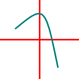
I want to ensure my logic is correct here, maybe someone here could help me out or give their input. I understand that the torque from an engine on a dyno is the torque that is produced at the crank, in other words, in the image below, that Max torque of 30.87 Lb foot is the torque that the engine produces at the crank.

Now my next step is to think alright well the drive goes through gearing with in gear one I have calculated is 1:32 for a '14 Crf250r. Hence, the crank does 32 rotations for even 1 rotation of the rear wheel, meaning the torque will be 32 times as high at the rear wheel as the crank. Which yields, 30.87lbft * 1:32 = 987.84lbft. I convert this to Nm so my head doesn't explode, which results in 1340Nm. Now my logic makes me think that if I was to apply 1340N at 1m from the center of rotation of the rear wheel, I should get correct performance, assuming full throttle.

I am aware im using gearing of a 250 and torque of a 450, but that's not my concern now, I am trying to figure out if my logic is correct.

Image

New next step, RPM.

What is proving to be a challenge, is the fact that the engine increases its rpm by adding air which adds fuel which raises the rpm, but it also goes the other way round, the wheel affects the engine, such as dropping the clutch in 5th gear on idle will almost certainly make the engine stall from the sudden drop in rpm due to insufficient torque. I am wondering, how can I calculate this whole rpm system, especially incorporating a clutch. At the moment I have the following.

RPM = WheelAngularVelocity * (1 / GearRatio)

AngularForceOnWheel (Nm) = Torque@RPM * Gear

The force increases the wheel speed which in turn increases the rpm and hence the system works, the problem is tho, its like constantly being in gear. And incorporating a clutch and achieving a natural idle for example is driving me insane. Any input will be appreciated!

Cheers guys!
yzmxer608
Posts: 15352
Joined: Mon Dec 29, 2008 4:30 am
Team: SYS
Location: Wisconsin, U.S.A

Re: The Math behind Internal Combustion

Post by yzmxer608 »

The torque from a dyno like that is at the rear wheel, not the crank. If you ever see the term "brake horsepower" that's the HP at the crank instead of the wheels, which is always higher because of losses due to friction etc (I don't believe there is a special term for torque at the crank though). This link explains what the dyno does and talks about relative equations, I suggest reading through all of it: http://www.epi-eng.com/piston_engine_te ... torque.htm

Although this doesn't have the new bikes as options, it may help you http://crfsonly.com/howto/gearing/motor ... ulator.php.

Your equation for engine RPM is close, you have to just multiply by the gear ratio, not it's inverse: Engine RPM=Wheel Angular Velocity (RPM)*Gear Ratio

Torque is defined as a force multiplied by a distance: T=F*D
Unit analysis using English units cause 'merica:
lb*ft=Torque in pound-foot.
So rearranging: F=T/D, again unit analysis:
lb*ft/ft=Force in pounds

That's it, just use the torque and the radius of the wheel with tire to get the force. You don't have to mess around with the gear ratio since the torque you're using in the equation is at the wheel not the crank. I'm not totally sure on the clutch part, the clutch just disengages the drive, so I'm thinking it could be a linear decrease from whatever the applied torque is at the rear wheel, to zero applied torque. In equation form that would look like:
T=F*D*Clutch Engagement
where Clutch Engagement is the percentage of engagement in decimal form, that's assuming the clutch engagement is linear, which I'm not completely sure it is.

But again like you said the problem is finding the engine RPM since the rear wheel is disengaged from the engine. I'm thinking that would have to be measured, since you can't really find what the engine rpm is, I don't think this equation would work:
Engine RPM=Wheel Angular Velocity (RPM)*Gear Ratio*(1+Clutch Engagement)

So for example, using a wheel angular velocity of 250 RPM (about 28MPH with a 19 inch rear wheel, I'm not sure what the diameter of an actual tire is) with your 32:1 gear ratio (from the opposite POV, engine RPM to wheel RPM, assuming the countershaft and wheel sprockets are included) with NO clutch:
Engine RPM=250 RPM*32*(1+0)=8,000 RPM
Now with 50% clutch engagement:
Engine RPM=250 RPM*32*(1+.5)=12,000 RPM
The RPM seems like it increases too much, but it may be correct considering it's very easy to hit the rev limiter pulling down a straight and engaging the clutch 100%. Let's see what other smarter people than me have to say (ahem, JLV) :lol:.
TeamHavocRacing wrote:If I had a nickel for every time someone asked for this, I would have a whole shitload of nickels.
cccccccc
Posts: 36
Joined: Thu Aug 30, 2012 9:06 pm
Location: Perth, WA, Australia

Re: The Math behind Internal Combustion

Post by cccccccc »

Seems like you need to add a parabolic arc(or some similar type arc) to the Clutching mechanism,


If the Engine is lugging a certain amount of clutching needs to be applied to achieve maximum 'torque or power or acceleration'
Too much clutch and the engine speed raises dramatically with zero torque at the rear wheel and no acceleration ( negative acceleration )


Ideally Riding the clutch a little bit will allow a slight extra speed gain
cccccccc
Posts: 36
Joined: Thu Aug 30, 2012 9:06 pm
Location: Perth, WA, Australia

Re: The Math behind Internal Combustion

Post by cccccccc »

Image

On the left the Clutch is fully Released
On the centre line the clutch is being slipped at the ideal amount to accelerate the quickest
On the Right the Clutch is Fully Pulled in

The vertical Axis represents Percentage of power at the rear wheel (Top = 100%, Bottom = 0%

Note that the arc isn't exact to real life and may be compressed or stretched at a given RPM
attacker5
Posts: 2226
Joined: Tue Aug 18, 2009 8:53 pm
Team: Ub e moh tow

Re: The Math behind Internal Combustion

Post by attacker5 »

Thanks a lot guys! I have taken it all in and im working hard on figuring out all the components. Il post soon with the results. :D
attacker5
Posts: 2226
Joined: Tue Aug 18, 2009 8:53 pm
Team: Ub e moh tow

Re: The Math behind Internal Combustion

Post by attacker5 »

One question Nate, you said that torque is the torque at the wheel, so lets say its 25Nm peak. Since the gear ratio from crank to wheel is 32:1, does that mean the crank's torque is 25/32? Because that results in .78Nm, which means the engine cant even list 1Kg, 10cm radius from the crank? Maybe I am understanding wrong.

Cheers
SMR 510RR
Posts: 2526
Joined: Sun Apr 08, 2012 6:36 am
Team: Privateer

Re: The Math behind Internal Combustion

Post by SMR 510RR »

You need to work backward from the wheel and the gear the Dyno run was performed in. Not sure about dirt bikes but for cars it will always be done in the gear closest to 1:1 ratio at the transmission in the case of a dirt bike that would be the tallest gear 5th for the CRF250R for a ratio of roughly 9:1 that changes the numbers dramatically vs. 32:1. Then you can find out what the engine torque is including losses (the losses would probably be less for shorter gears but not sure how much it really matters) and do the math to find the force for each gear.

As far as figuring out the RPM not sure if there is really a way to do it because the RPM graph is not scaled in time. In my mind the best way would be to plot the curve and find the equation that best describes it, then you can solve for Y along X at a given interval (say every 500RPM) and then use that as a multiplier along with a known length of time the pull took (should be decent based of a video of a similar bike) to find how fast the RPM changes based on the torque the engine is producing at that point in time. It could be way off but should at least get you a starting point to tweak from. There was a good dyno video posted a few weeks back with fairly clean sound that may be helpful to judge the RPM based on the pitch of the Exhaust, this would give you RPM at a time interval that you could then match back up to the torque.

The clutch is a tough one, I wonder if there are any graphs comparing lever (or pedal) position to friction that could give you a decent idea what that even looks like. A brake graph may be helpful in the absence of a clutch specific graph since they are similar concepts and both use friction material under pressure against a smooth generally metallic surface. Once you know the friction you could then reevaluate what would happen to the RPMs and torque level for different clutch positions.

It is a interesting problem. Hopefully that made sense, its sort of a hard thing to describe.
SMR 510RR
Posts: 2526
Joined: Sun Apr 08, 2012 6:36 am
Team: Privateer

Re: The Math behind Internal Combustion

Post by SMR 510RR »

I realized while trying to fall asleep last night that the whole middle part is completely unnecessary and was something I dreamed up a while back to get sounds from dyno runs. Ignore it haha.
yzmxer608
Posts: 15352
Joined: Mon Dec 29, 2008 4:30 am
Team: SYS
Location: Wisconsin, U.S.A

Re: The Math behind Internal Combustion

Post by yzmxer608 »

attacker5 wrote:One question Nate, you said that torque is the torque at the wheel, so lets say its 25Nm peak. Since the gear ratio from crank to wheel is 32:1, does that mean the crank's torque is 25/32? Because that results in .78Nm, which means the engine cant even list 1Kg, 10cm radius from the crank? Maybe I am understanding wrong.

Cheers
I had to double check and the math for that looks right but .78Nm seems way too low. Maybe that dyno converts it to torque at the crank using gear ratio input by the technician? I'm not sure now...
TeamHavocRacing wrote:If I had a nickel for every time someone asked for this, I would have a whole shitload of nickels.
wheels1758
Posts: 4132
Joined: Tue Oct 21, 2008 5:20 pm
Location: Washington, USA
Contact:

Re: The Math behind Internal Combustion

Post by wheels1758 »

Call me crazy, but any horsepower/torque curve that is not corrected (via gear ratio) to the crank would then be a "Torque in X gear" graph, correct? I would assume that the curve provided is actually HP/Torque at the crank, i.e. "This is the power the engine makes no matter which gear you are in" graph.
ddmx
Posts: 5374
Joined: Sun Apr 20, 2008 3:36 pm
Location: Midland MI

Re: The Math behind Internal Combustion

Post by ddmx »

+1 on wheels' comment.
ddmx
Posts: 5374
Joined: Sun Apr 20, 2008 3:36 pm
Location: Midland MI

Re: The Math behind Internal Combustion

Post by ddmx »

Before we go all physics and waste our energy... to what level of detail are you trying to model this engine? If you're trying to capture all the effects of friction, intertia, losses, etc.. This can (and will) get very complicated quite quickly.
SMR 510RR
Posts: 2526
Joined: Sun Apr 08, 2012 6:36 am
Team: Privateer

Re: The Math behind Internal Combustion

Post by SMR 510RR »

Hmm, that is interesting I hadn't even thought that the Dyno corrects for ratio by comparing the engine and drum RPM and does the resulting math for you. I guess the 1:1 ratio thing is just the most efficient gear because large/small combos have more inherent losses.

Some discussion about it for cars but it should be no different.
http://www.corvetteforum.com/forums/c5- ... mbers.html
attacker5
Posts: 2226
Joined: Tue Aug 18, 2009 8:53 pm
Team: Ub e moh tow

Re: The Math behind Internal Combustion

Post by attacker5 »

ddmx wrote:Before we go all physics and waste our energy... to what level of detail are you trying to model this engine? If you're trying to capture all the effects of friction, intertia, losses, etc.. This can (and will) get very complicated quite quickly.
Well, not so much in the small energy parts, but rather believable output. For example, take rfactor. I know that's aiming a little high and I don't expect that result, but I can only score as high as I aim.

I have worked on the model a lot and have come up with a fairly good simulation to build from. Note, the curves and the suspension adjustments are off by far, I am messing with everything, but should give a good idea of the reaction of the power to rpm and such, as you can see in the telemetry.

m121c
Posts: 3056
Joined: Sun Feb 27, 2011 5:36 am
Location: Iowa

Re: The Math behind Internal Combustion

Post by m121c »

#Canadacustomstories
Post Reply