So I have been doing a little analysis on a Honda Crf250r 2016, and I started with the shock spring. After a bit, I thought why not post it, maybe someone finds it interesting.
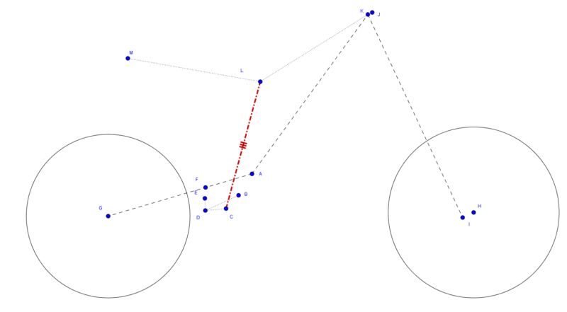
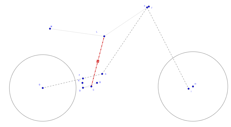
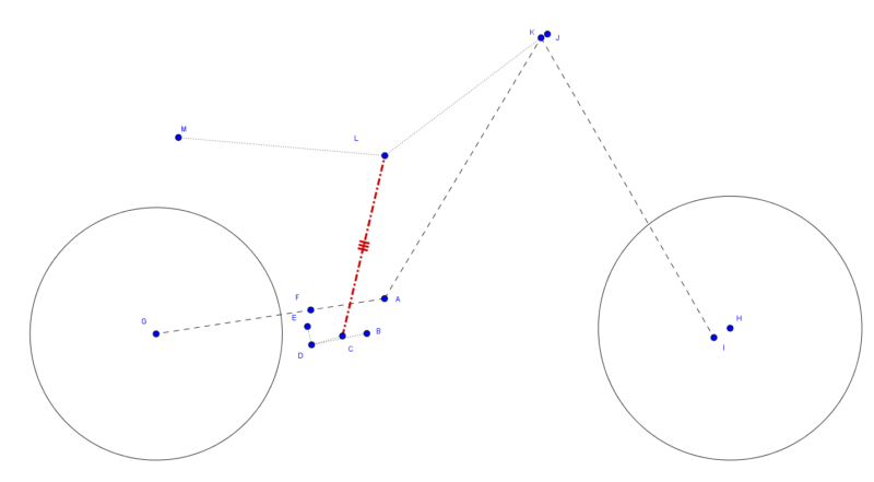
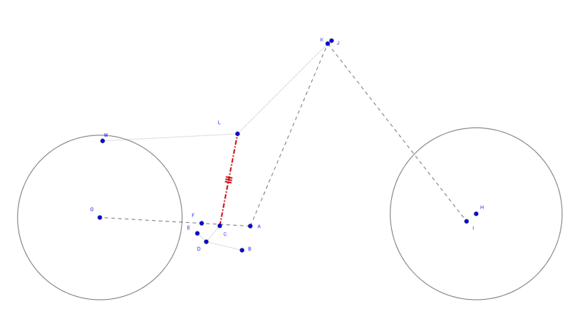
Lets start with the diagram. These 4 images show the Crf rear suspension compressed from Freehang to Bottom Out. The second image is the static sag compression (The bike squatting under its own weight), and the third image shows something in between simply to make visualizing the linkage movement easier. An important thing to note also, the forks are locked, and do not compress at all.
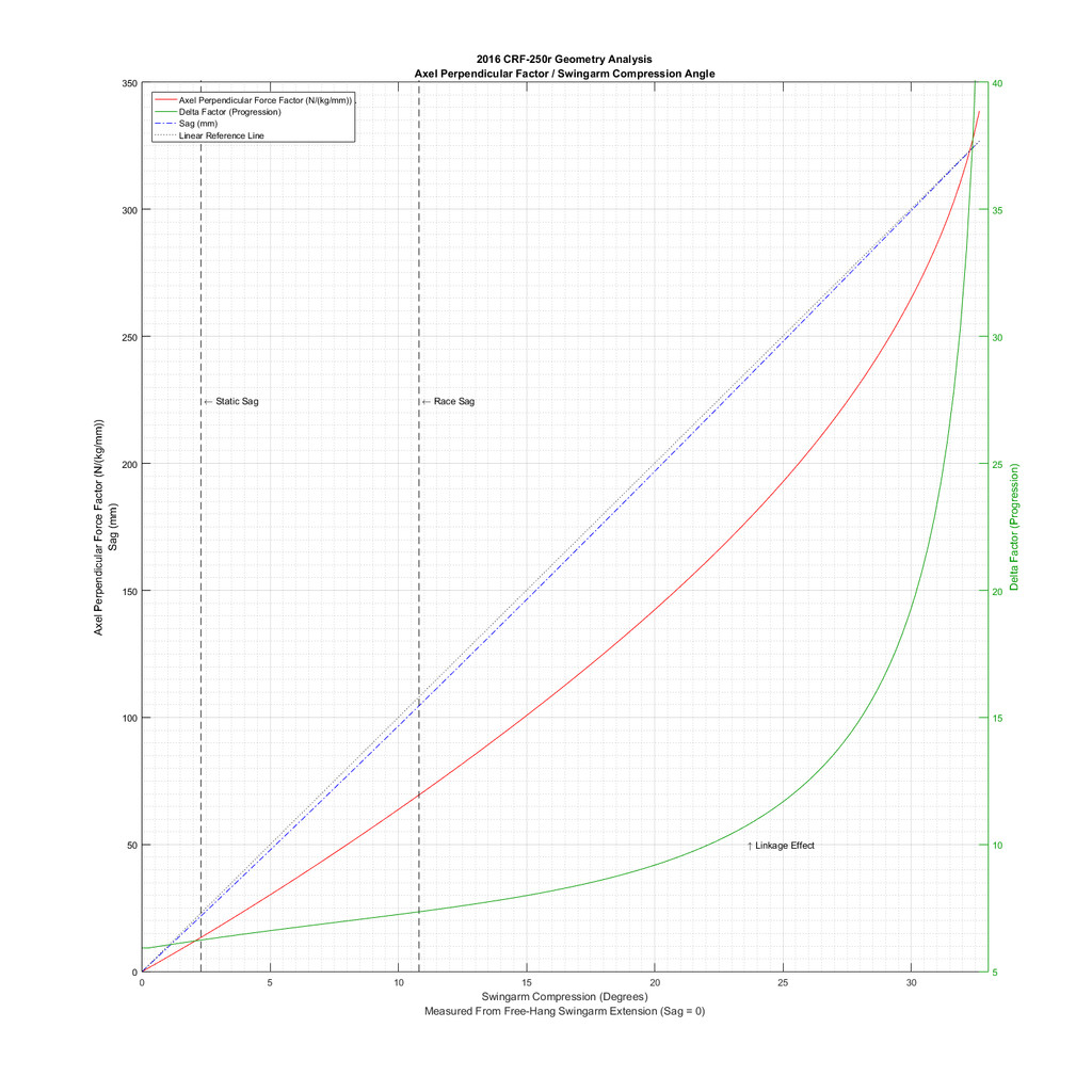
So this first graph is the overview graph showing the curve of the resultant spring force on the rear axle, perpendicular to the wheelAxle-swingarmAxle line. This is assuming a linkage bone length of 142mm and a lower linkage length of 78mm. This will be more clear later.
Notice also how the Sag is not linear, this is due to the fact that the measuring point (the mark on the rear fender) actually moves in an arc towards the rear axle.
The unit of the force is a little unintuitive. It is the factor of force multiplied by 9.81 to get Newton, but not multiplied by a spring rate. So take this value and multiply it by the spring rate in Kg/mm to get the total force in Newtons.
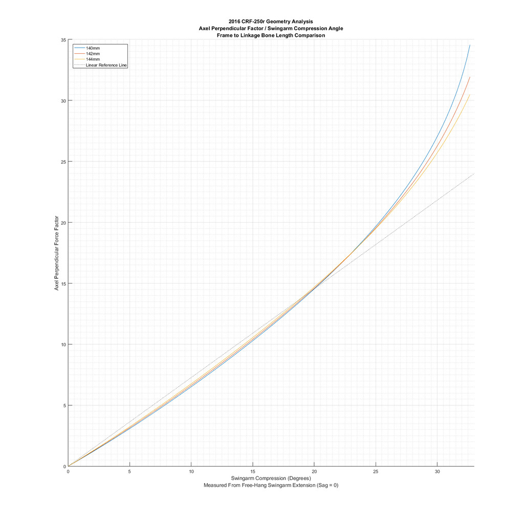
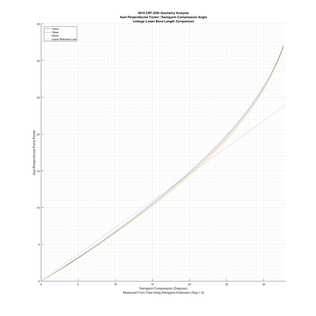
The next 2 graphs compare linkages of different dimensions. The first compares the difference of Dog Bones (D to B) ranging from 140mm to 144mm. Note a lower linkage length (D to C) of 78mm was used, the standard.
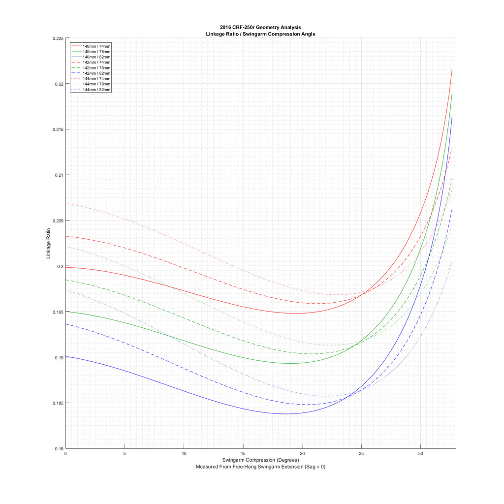
This last graph shows how to linkages affect the force and leverage ratio. Basically, the point where the spring applies the force isn't constant. So the linkage not only changes how fast the spring compresses as it goes through a stroke, it also changes how much effect the spring has on the rear axle.
Multiply the spring force calculated above by this factor to get the perpendicular force at the rear axle.
That is all for now folks. I hope someone finds this interesting, I sure do!
Cheers,
On to damping now!
